Textbook Question
A series RLC circuit consists of a 75 Ω resistor, a 0.12 H inductor, and a 30 μF capacitor. It is attached to a 120 V/60 Hz power line. What is the peak current I?
1
views

 Verified step by step guidance
 08:32
08:32 07:50
07:50 08:40
08:40A series RLC circuit consists of a 75 Ω resistor, a 0.12 H inductor, and a 30 μF capacitor. It is attached to a 120 V/60 Hz power line. What is the peak current I?
You have a resistor and a capacitor of unknown values. First, you charge the capacitor and discharge it through the resistor. By monitoring the capacitor voltage on an oscilloscope, you see that the voltage decays to half its initial value in 2.5 ms. You then use the resistor and capacitor to make a low-pass filter. What is the crossover frequency fc?
The small transformers that power many consumer products produce a 12.0 V rms, 60 Hz emf. Design a circuit using resistors and capacitors that uses the transformer voltage as an input and produces a 6.0 V rms output that leads the input voltage by 45°.
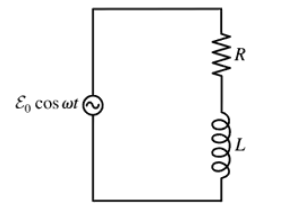
Use a phasor diagram to analyze the RL circuit of FIGURE P32.49. In particular, Find an expression for the crossover frequency ωc.
Use a phasor diagram to analyze the RL circuit of FIGURE P32.49. In particular, Find expressions for I, VR, and VL.
A series RL circuit is built with a 110 Ω resistor and a 5.0-cm-long, 1.0-cm-diameter solenoid with 800 turns of wire. What is the peak magnetic flux through the solenoid if the circuit is driven by a 12 V, 5.0 kHz source?