Ch 30: Electromagnetic Induction
Knight Calc - Physics for Scientists and Engineers 5th Edition
Knight Calc5th EditionPhysics for Scientists and EngineersISBN: 9780137344796Not the one you use?Change textbook
Chapter 30, Problem 76a

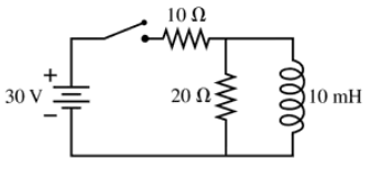
The switch in FIGURE P30.76 has been open for a long time. It is closed at t = 0 s. What is the current through the 20 Ω resistor immediately after the switch is closed?

Verified step by step guidance
1
Step 1: Analyze the circuit configuration. The circuit consists of a 30 V battery, a 10 Ω resistor, a 20 Ω resistor, and a 10 mH inductor. The switch has been open for a long time, meaning the inductor has no initial current flowing through it. When the switch is closed at t = 0 s, the inductor will oppose any sudden change in current due to its inductive property.
Step 2: Understand the behavior of the inductor immediately after the switch is closed. At t = 0 s, the inductor behaves like an open circuit because it resists any instantaneous change in current. Therefore, no current flows through the branch containing the inductor at this instant.
Step 3: Simplify the circuit for t = 0 s. Since the inductor acts as an open circuit, the 20 Ω resistor is effectively disconnected from the circuit. The current flows only through the 10 Ω resistor connected directly to the battery.
Step 4: Apply Ohm's Law to calculate the current through the 10 Ω resistor. The voltage across the resistor is equal to the battery voltage (30 V). Using Ohm's Law, \( I = \frac{V}{R} \), where \( V \) is the voltage and \( R \) is the resistance.
Step 5: Conclude that the current through the 20 Ω resistor is zero immediately after the switch is closed because the inductor prevents current from flowing through its branch at t = 0 s.

Verified video answer for a similar problem:

This video solution was recommended by our tutors as helpful for the problem above.
Was this helpful?

Key Concepts

Here are the essential concepts you must grasp in order to answer the question correctly.

Ohm's Law

Ohm's Law states that the current (I) through a conductor between two points is directly proportional to the voltage (V) across the two points and inversely proportional to the resistance (R) of the conductor. This relationship is expressed mathematically as I = V/R. Understanding this law is crucial for calculating the current through resistors in a circuit.
Recommended video:
Guided course
03:07
Resistance and Ohm's Law

Inductance and Inductive Reactance

Inductance is a property of an electrical component, typically a coil or inductor, that opposes changes in current. When the switch is closed, the inductor initially resists the change in current, creating a transient response. The inductive reactance (XL) can be calculated using the formula XL = 2πfL, where f is the frequency and L is the inductance. However, immediately after closing the switch, the inductor behaves like a short circuit.
Recommended video:
Guided course
12:59
Mutual Induction

Transient Response in RL Circuits

In an RL circuit, when a switch is closed, the current does not instantly reach its maximum value due to the inductor's opposition to changes in current. Instead, the current increases gradually, following an exponential curve characterized by the time constant τ = L/R, where L is the inductance and R is the total resistance in the circuit. Analyzing the transient response is essential for understanding the behavior of the circuit immediately after the switch is closed.
Recommended video: