Textbook Question
The switch in FIGURE P30.76 has been open for a long time. It is closed at t = 0 s. What is the current through the 20 Ω resistor after the switch has been closed a long time?

 Verified step by step guidance
 08:02
08:02 05:43
05:43 07:14
07:14The switch in FIGURE P30.76 has been open for a long time. It is closed at t = 0 s. What is the current through the 20 Ω resistor after the switch has been closed a long time?
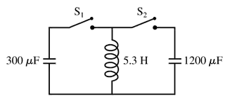
An electric oscillator is made with a 0.10 μF capacitor and a 1.0 mH inductor. The capacitor is initially charged to 5.0 V. What is the maximum current through the inductor as the circuit oscillates?
The switch in FIGURE P30.76 has been open for a long time. It is closed at t = 0 s. What is the current through the 20 Ω resistor immediately after the switch is closed?
The switch in FIGURE P30.77 has been open for a long time. It is closed at t = 0 s. After the switch has been closed for a long time, what is the current in the circuit? Call this current I0.
An LC circuit is built with a 20 mH inductor and an 8.0 pF capacitor. The capacitor voltage has its maximum value of 25 V at t = 0 s. What is the inductor current at that time?
CALC The current through inductance L is given by . Evaluate ΔVL at t = 0, 1.0, and 3.0 ms if L = 20 mH, I0 = 50 mA, and = 1.0 ms.