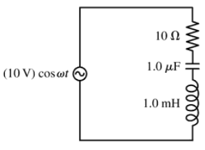
Ch 32: AC Circuits
Knight Calc - Physics for Scientists and Engineers 5th Edition
Knight Calc5th EditionPhysics for Scientists and EngineersISBN: 9780137344796Not the one you use?Change textbook
Chapter 32, Problem 33a

For the circuit of FIGURE EX32.33, What is the resonance frequency, in both rad/s and Hz?

Verified step by step guidance
1
Step 1: Identify the components in the circuit. The circuit consists of a resistor (R = 10 Ω), a capacitor (C = 1.0 μF), and an inductor (L = 1.0 mH) connected in series with an AC voltage source.
Step 2: Recall the formula for the resonance frequency in a series RLC circuit. Resonance occurs when the inductive reactance and capacitive reactance cancel each other out. The resonance angular frequency (ω₀) is given by: ω₀ = 1 / √(L * C).
Step 3: Substitute the given values for L and C into the formula. Convert the units to SI: L = 1.0 mH = 1.0 × 10⁻³ H, and C = 1.0 μF = 1.0 × 10⁻⁶ F.
Step 4: Calculate the resonance angular frequency (ω₀) using the formula ω₀ = 1 / √(L * C). This will give the resonance frequency in radians per second (rad/s).
Step 5: Convert the angular frequency (ω₀) to the resonance frequency in hertz (f₀) using the relationship f₀ = ω₀ / (2π).

Verified video answer for a similar problem:

This video solution was recommended by our tutors as helpful for the problem above.
Was this helpful?

Key Concepts

Here are the essential concepts you must grasp in order to answer the question correctly.

Resonance Frequency

Resonance frequency is the frequency at which a system naturally oscillates with maximum amplitude. In an RLC circuit, it occurs when the inductive reactance equals the capacitive reactance, leading to a condition where the impedance is minimized. This frequency can be calculated using the formula f₀ = 1/(2π√(LC)), where L is inductance and C is capacitance.
Recommended video:
Guided course
05:23
Resonance in Series LRC Circuits

Inductive Reactance

Inductive reactance (X_L) is the opposition that an inductor presents to alternating current (AC) due to its inductance. It is calculated using the formula X_L = ωL, where ω is the angular frequency in rad/s and L is the inductance in henries. This concept is crucial for determining the behavior of the circuit at different frequencies, especially at resonance.
Recommended video:
Guided course
12:59
Mutual Induction

Capacitive Reactance

Capacitive reactance (X_C) is the opposition that a capacitor presents to AC, which decreases with increasing frequency. It is given by the formula X_C = 1/(ωC), where C is the capacitance in farads. Understanding capacitive reactance is essential for analyzing the resonance condition in RLC circuits, as it directly influences the overall impedance and phase relationships in the circuit.
Recommended video:
Guided course
08:02
Capacitors & Capacitance (Intro)