Textbook Question
A series RLC circuit consists of a 75 Ω resistor, a 0.12 H inductor, and a 30 μF capacitor. It is attached to a 120 V/60 Hz power line. What is the peak current I?
1
views

 Verified step by step guidance
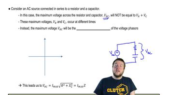
 08:40
08:40 07:14
07:14 05:23
05:23A series RLC circuit consists of a 75 Ω resistor, a 0.12 H inductor, and a 30 μF capacitor. It is attached to a 120 V/60 Hz power line. What is the peak current I?
Use a phasor diagram to analyze the RL circuit of FIGURE P32.49. In particular, Find an expression for the crossover frequency ωc.
A series RLC circuit consists of a 75 Ω resistor, a 0.12 H inductor, and a 30 μF capacitor. It is attached to a 120 V/60 Hz power line. What is the average power dissipated?
A series RL circuit is built with a 110 Ω resistor and a 5.0-cm-long, 1.0-cm-diameter solenoid with 800 turns of wire. What is the peak magnetic flux through the solenoid if the circuit is driven by a 12 V, 5.0 kHz source?
In FIGURE P32.54, what is the current supplied by the emf when (a) the frequency is very small and (b) the frequency is very large?
A series RLC circuit consists of a 50 Ω resistor, a 3.3 mH inductor, and a 480 nF capacitor. It is connected to a 5.0 kHz oscillator with a peak voltage of 5.0 V. What is the instantaneous current i when ε = ε0?