Ch 30: Electromagnetic Induction
Knight Calc - Physics for Scientists and Engineers 5th Edition
Knight Calc5th EditionPhysics for Scientists and EngineersISBN: 9780137344796Not the one you use?Change textbook
Chapter 30, Problem 32b

The switch in FIGURE EX30.32 has been in position 1 for a long time. It is changed to position 2 at t = 0 s. What is the first time at which the current is maximum?

Verified step by step guidance
1
Step 1: Analyze the circuit. When the switch is in position 1 for a long time, the capacitor charges to the voltage of the battery (12 V). The resistor limits the charging current, but after a long time, the capacitor is fully charged, and no current flows through the resistor.
Step 2: When the switch is moved to position 2 at t = 0 s, the charged capacitor begins to discharge through the inductor, forming an LC circuit. This creates an oscillatory current due to the energy exchange between the capacitor and the inductor.
Step 3: The oscillation frequency of the LC circuit is determined by the formula \( f = \frac{1}{2\pi\sqrt{LC}} \), where \( L \) is the inductance (50 mH) and \( C \) is the capacitance (2.0 \( \mu \text{F} \)). Calculate the angular frequency \( \omega \) using \( \omega = \sqrt{\frac{1}{LC}} \).
Step 4: The current in the LC circuit reaches its maximum when the capacitor is fully discharged, and all the energy is stored in the inductor. This occurs at a quarter of the oscillation period \( T \), where \( T = \frac{1}{f} \). Use \( T = 2\pi\sqrt{LC} \) to find the period, and divide it by 4 to find the first time at which the current is maximum.
Step 5: Substitute the values of \( L = 50 \text{ mH} \) and \( C = 2.0 \mu \text{F} \) into the formulas to calculate the oscillation period and the time at which the current is maximum. Ensure units are consistent (convert \( \mu \text{F} \) to \( \text{F} \) and \( \text{mH} \) to \( \text{H} \)).

Verified video answer for a similar problem:

This video solution was recommended by our tutors as helpful for the problem above.
Was this helpful?

Key Concepts

Here are the essential concepts you must grasp in order to answer the question correctly.

RL Circuit Dynamics

An RL circuit consists of a resistor (R) and an inductor (L) connected in series or parallel. When the switch in the circuit is changed, the inductor resists changes in current due to its stored magnetic energy. The time constant, which is the time taken for the current to reach approximately 63% of its maximum value, is determined by the ratio of inductance to resistance (L/R). Understanding this behavior is crucial for analyzing the transient response of the circuit.
Recommended video:
Guided course
08:12
Torque & Acceleration (Rotational Dynamics)

Capacitor Charging and Discharging

Capacitors store electrical energy in an electric field and can charge and discharge through a circuit. The charging process follows an exponential curve, where the voltage across the capacitor increases over time until it reaches the supply voltage. The time constant for a capacitor is defined as the product of resistance and capacitance (RC), which dictates how quickly the capacitor charges or discharges. This concept is essential for determining the current behavior when the switch is moved.
Recommended video:
Guided course
06:07
Point Charge Inside Capacitor

Maximum Current in Transient Circuits

In transient circuits, the maximum current occurs when the circuit reaches a steady state after the switch is toggled. For an RL circuit, the maximum current can be calculated using Ohm's law, where the maximum current (I_max) is equal to the voltage divided by the total resistance in the circuit. The timing of when this maximum current occurs is influenced by the inductance and resistance, and it is critical to analyze the circuit's response to determine when this peak current is achieved.
Recommended video:
Guided course
03:45
Current in a Parallel RC AC Circuit
Related Practice
Textbook Question

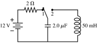
At t = 0 s, the current in the circuit in FIGURE EX30.35 is I0. At what time in μs is the current (1/2)I0?

1
views
Textbook Question

CALC A 10 cm×10 cm square loop of wire lies in the xy-plane. The magnetic field in this region of space is B=(0.30ti^+0.50t2k^) T\(\vec{B}\) = (0.30t\(\hat{i}\) + 0.50t^2\(\hat{k}\))\(\text{ T}\), where t is in s. What is the emf induced in the loop at (a) t = 0.5 s and (b) t = 1.0 s?

2
views
Textbook Question

A 2.0 mH inductor is connected in parallel with a variable capacitor. The capacitor can be varied from 100 pF to 200 pF. What is the range of oscillation frequencies for this circuit?

1
views
Textbook Question

BIO MRI (magnetic resonance imaging) is a medical technique that produces detailed 'pictures' of the interior of the body. The patient is placed into a solenoid that is 40 cm in diameter and 1.0 m long. A 100 A current creates a 5.0 T magnetic field inside the solenoid. To carry such a large current, the solenoid wires are cooled with liquid helium until they become superconducting (no electric resistance). How much magnetic energy is stored in the solenoid? Assume that the magnetic field is uniform within the solenoid and quickly drops to zero outside the solenoid.

2
views
Textbook Question

BIO An MRI machine needs to detect signals that oscillate at very high frequencies. It does so with an LC circuit containing a 15 mH coil. To what value should the capacitance be set to detect a 450 MHz signal?

1
views
Textbook Question

A 100-turn, 2.0-cm-diameter coil is at rest with its axis vertical. A uniform magnetic field 60° away from vertical increases from 0.50 T to 1.50 T in 0.60 s. What is the induced emf in the coil?

1
views