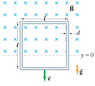
In an experiment, a coil was mounted on a low-friction cart that moved through the magnetic field B of a permanent magnet. The speed of the cart v and the induced voltage V were simultaneously measured, as the cart moved through the magnetic field, using a computer-interfaced motion sensor and a voltmeter. The Table below shows the collected data:
Make a graph of the induced voltage, V, vs. the speed, v. Determine a best-fit linear equation for the data. Theoretically, the relationship between V and v is given by V = BN𝓁𝓋 where N is the number of turns of the coil, B is the magnetic field, and ℓ is the average of the inside and outside widths of the coil. In the experiment, B = 0.126 T, N = 50, and ℓ = 0.0561 m.


 12:59
12:59