Ch. 12 - Static Equilibrium; Elasticity and Fracture
Giancoli Douglas - Physics for Scientists and Engineers 5th edition
Giancoli Douglas5th editionPhysics for Scientists and EngineersISBN: 9780137488179Not the one you use?Change textbook
Chapter 12, Problem 83b

A uniform beam of mass M and length ℓ is mounted on a hinge at a wall as shown in Fig. 12–101. It is held in a horizontal position by a wire making an angle θ as shown. A mass m is placed on the beam a distance x from the wall, and this distance can be varied. Determine, as a function of x, the components of the force exerted by the beam on the hinge.
Diagram of a beam hinged to a wall, with a mass on it and a wire at an angle, illustrating rotational equilibrium concepts.

Verified step by step guidance
1
Step 1: Identify the forces acting on the beam. These include: (1) the gravitational force acting on the beam itself, which is located at its center of mass (at a distance ℓ/2 from the hinge), (2) the gravitational force due to the mass m placed on the beam at a distance x from the hinge, (3) the tension T in the wire acting at an angle θ, and (4) the reaction forces at the hinge, which have horizontal (F_h) and vertical (F_v) components.
Step 2: Write the torque equilibrium equation about the hinge. Since the beam is in static equilibrium, the sum of torques about the hinge must be zero. The torque contributions are: (1) the torque due to the beam's weight Mg, (2) the torque due to the weight of the mass m, and (3) the torque due to the tension T in the wire. Use the equation: Στ = 0, where τ = r × F. The distances from the hinge to the points of application of these forces are ℓ/2, x, and ℓ, respectively.
Step 3: Write the force equilibrium equations. Since the beam is in static equilibrium, the sum of forces in both the horizontal and vertical directions must be zero. For the vertical direction: ΣF_y = 0, which includes the upward vertical component of the tension (Tsinθ) and the downward forces due to the beam's weight (Mg) and the weight of the mass m (mg). For the horizontal direction: ΣF_x = 0, which includes the horizontal component of the tension (Tcosθ) and the horizontal reaction force at the hinge (F_h).
Step 4: Solve for the tension T in the wire using the torque equilibrium equation. Substitute the expressions for the torques due to the beam's weight, the weight of the mass m, and the tension in the wire. Rearrange the equation to isolate T as a function of x, M, m, ℓ, g, and θ.
Step 5: Solve for the components of the force exerted by the hinge. Use the force equilibrium equations to find F_h and F_v. Substitute the expression for T obtained in Step 4 into these equations. Express F_h and F_v in terms of the given variables (M, m, ℓ, g, θ, and x).

Verified video answer for a similar problem:

This video solution was recommended by our tutors as helpful for the problem above.
Video duration:
12m
Was this helpful?

Key Concepts

Here are the essential concepts you must grasp in order to answer the question correctly.

Torque

Torque is a measure of the rotational force applied to an object, calculated as the product of the force and the distance from the pivot point (hinge) to the point of force application. In this scenario, the beam experiences torque due to its weight and the weight of the mass m placed on it. Understanding how to calculate torque is essential for analyzing the equilibrium of the beam.
Recommended video:
Guided course
08:55
Net Torque & Sign of Torque

Equilibrium

Equilibrium occurs when the sum of all forces and the sum of all torques acting on an object are zero, resulting in a state of rest or constant motion. For the beam in this problem, it must be in static equilibrium, meaning the upward tension in the wire and the downward gravitational forces must balance out, and the torques about the hinge must also balance. This concept is crucial for determining the conditions under which the beam remains horizontal.
Recommended video:
Guided course
10:13
Torque & Equilibrium

Force Components

Force components refer to the breakdown of a force into its horizontal and vertical parts, which can be analyzed separately. In this problem, the tension in the wire can be resolved into components that affect both the vertical and horizontal forces acting on the beam. Understanding how to resolve forces into components is vital for applying Newton's laws and analyzing the forces at play in the system.
Recommended video:
Guided course
07:30
Vector Addition By Components
Related Practice
Textbook Question

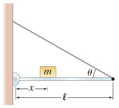
A uniform 95-kg flagpole of length 8.4 m is being erected by pulling on a rope attached 2/3 of the way to the top (Fig. 12–94). When the pole is inclined at 35° and the rope makes an angle with the ground of 18°, what is the tension in the rope?

2
views
Textbook Question

A steel rod of radius R = 15 cm and length ℓ₀ stands upright on a firm surface. A 78-kg man climbs atop the rod. When a metal is compressed, each atom throughout its bulk moves closer to its neighboring atom by exactly the same fractional amount. If iron atoms in steel are normally 2.0 x 10⁻¹⁰ m apart, by what distance did this interatomic spacing have to change in order to produce the normal force required to support the man? [Note: Neighboring atoms repel each other, and this repulsion accounts for the observed normal force.]

3
views
Textbook Question

Suppose a 65-kg person jumps from a height of 3.0 m down to the ground. Estimate the stress and determine if the tibia will break in a stiff-legged landing (d = 1.0 cm).

2
views
Textbook Question

If 25 kg is the maximum mass m that a person can hold in a hand when the arm is positioned with a 105° angle at the elbow as shown in Fig. 12–102, what is the maximum force Fₘₐₓ that the biceps muscle exerts on the forearm? Assume the forearm and hand have a total mass of 2.0 kg with a cg that is 15 cm from the elbow, and that the biceps muscle attaches 5.0 cm from the elbow.

2
views
Textbook Question

A 25-kg object is being lifted by two people pulling on the ends of a 1.15-mm-diameter nylon cord that goes over two 3.00-m-high poles that are 4.5 m apart, as shown in Fig. 12–93. How high above the floor will the object be when the cord breaks?

1
views