Textbook Question
A series ac circuit contains a 250-Ω resistor, a 15-mH inductor, a 3.5-μF capacitor, and an ac power source of voltage amplitude 45 V operating at an angular frequency of 360 rad/s.What is the power factor of this circuit?
2
views

 Verified step by step guidance
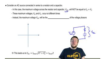
 08:40
08:40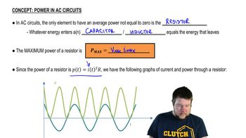 05:37
05:37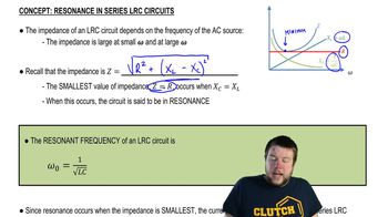 05:23
05:23A series ac circuit contains a 250-Ω resistor, a 15-mH inductor, a 3.5-μF capacitor, and an ac power source of voltage amplitude 45 V operating at an angular frequency of 360 rad/s.What is the power factor of this circuit?
An L-R-C series circuit with L = 0.120 H, R = 240 Ω, and C = 7.30 μF carries an rms current of 0.450 A with a frequency of 400 Hz. What are the phase angle and power factor for this circuit?
An L-R-C series circuit is connected to a 120-Hz ac source that has Vrms = 80.0 V. The circuit has a resistance of 75.0 Ω and an impedance at this frequency of 105 Ω. What average power is delivered to the circuit by the source?
A resistor with R = 300 Ω and an inductor are connected in series across an ac source that has voltage amplitude 500 V. The rate at which electrical energy is dissipated in the resistor is 286 W. What is (a) the impedance Z of the circuit; (b) the amplitude of the voltage across the inductor; (c) the power factor?
The power of a certain CD player operating at 120 V rms is 20.0 W. Assuming that the CD player behaves like a pure resistor, find the maximum instantaneous power.
You have a 200-Ω resistor, a 0.400-H inductor, and a 6.00-μF capacitor. They are connected to form an L-R-C series circuit. What is the current amplitude?