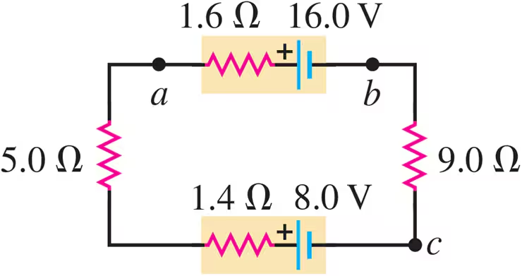
Ch 25: Current, Resistance, and EMF
Young & Freedman Calc - University Physics 15th Edition
Young & Freedman Calc15th EditionUniversity PhysicsISBN: 9780135159552Not the one you use?Change textbook
Chapter 25, Problem 39a

Consider the circuit of Fig. E25.30. What is the total rate at which electrical energy is dissipated in the 5.0 Ω and 9.0 Ω resistors?

Verified step by step guidance
1
First, identify the resistors in the circuit that are relevant to the problem. The problem asks for the power dissipated in the 5.0-Ω and 9.0-Ω resistors. However, the image does not show these resistors directly. We need to analyze the circuit to find the equivalent resistance and current through the circuit.
Calculate the total voltage in the circuit. The circuit has two batteries: one with 12.0 V and another with 7.50 V. Since they are in series, the total voltage is the sum of these two voltages. Use the formula: V=V1+V2.
Determine the total resistance in the circuit. The resistors are in series, so the total resistance is the sum of all resistors: 3.2 Ω, 1.0 Ω, 7.0 Ω, and 4.0 Ω. Use the formula: Rtotal=R1+R2+R3+R4.
Calculate the current flowing through the circuit using Ohm's Law, which states that I=VR. Substitute the total voltage and total resistance into this formula to find the current.
Finally, calculate the power dissipated in each resistor using the formula for power: P=I2R. Apply this formula to each resistor individually to find the power dissipated in the 5.0-Ω and 9.0-Ω resistors, if they were present. Since the image does not show these resistors, focus on the resistors given in the image.

Verified video answer for a similar problem:

This video solution was recommended by our tutors as helpful for the problem above.
Video duration:
6m
Was this helpful?

Key Concepts

Here are the essential concepts you must grasp in order to answer the question correctly.

Ohm's Law

Ohm's Law is fundamental in circuit analysis, stating that the current (I) through a conductor between two points is directly proportional to the voltage (V) across the two points and inversely proportional to the resistance (R) of the conductor. It is expressed as V = IR, and is essential for calculating current in each resistor to determine power dissipation.
Recommended video:
Guided course
03:07
Resistance and Ohm's Law

Power Dissipation in Resistors

Power dissipation in resistors is the rate at which electrical energy is converted into heat, calculated using the formula P = I^2R, where P is power, I is current, and R is resistance. Understanding this concept is crucial for determining how much energy is lost in the 5.0-Ω and 9.0-Ω resistors in the circuit.
Recommended video:
Guided course
06:18
Power in Circuits

Kirchhoff's Voltage Law

Kirchhoff's Voltage Law states that the sum of the electrical potential differences (voltage) around any closed network is zero. This principle helps in analyzing complex circuits by allowing the calculation of unknown voltages and currents, ensuring that the total voltage supplied equals the total voltage drop across the circuit components.
Recommended video:
Guided course
04:08
Kirchhoff's Junction Rule