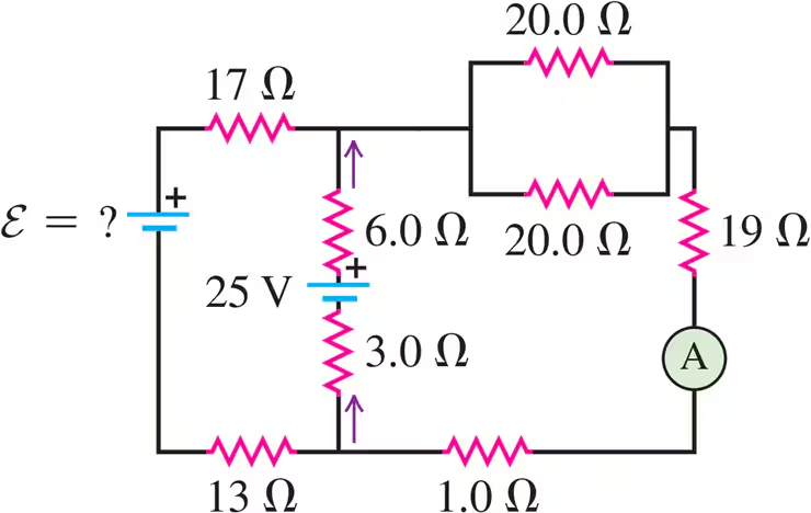
Ch 26: Direct-Current Circuits
Young & Freedman Calc - University Physics 14th Edition
Young & Freedman Calc14th EditionUniversity PhysicsISBN: 9780321973610Not the one you use?Change textbook
Chapter 26, Problem 34b

In the circuit shown in Fig. E26.34, the 6.0 Ω resistor is consuming energy at a rate of 24 J/s when the current through it flows as shown. What are the polarity and emf ε of the unknown battery, assuming it has negligible internal resistance?

Verified step by step guidance
1
First, understand that the power consumed by the resistor is given by the formula: P=I2R, where P is the power, I is the current, and R is the resistance.
Given that the power P is 24 J/s and the resistance R is 6.0 Ω, use the formula to solve for the current I: I=PR.
Once you have the current, apply Kirchhoff's loop rule to the circuit. This rule states that the sum of the potential differences (voltage) around any closed loop in a circuit must be zero.
Identify the direction of the current flow and the polarity of the known battery in the circuit. Use the loop rule to write an equation that includes the emf ε of the unknown battery, the voltage drop across the resistor, and any other known voltages.
Solve the equation for the unknown emf ε. The sign of ε will indicate the polarity of the unknown battery. If ε is positive, the polarity is in the direction of the assumed current flow; if negative, it is opposite.

Verified video answer for a similar problem:

This video solution was recommended by our tutors as helpful for the problem above.
Was this helpful?

Key Concepts

Here are the essential concepts you must grasp in order to answer the question correctly.

Ohm's Law

Ohm's Law states that the current through a conductor between two points is directly proportional to the voltage across the two points, and inversely proportional to the resistance. It is expressed as V = IR, where V is voltage, I is current, and R is resistance. This law is essential for calculating the current and voltage in the circuit.
Recommended video:
Guided course
03:07
Resistance and Ohm's Law

Power in Electrical Circuits

Power in electrical circuits is the rate at which energy is consumed or converted. It is calculated using the formula P = IV, where P is power, I is current, and V is voltage. Alternatively, it can be expressed as P = I^2R or P = V^2/R, depending on known values. Understanding power consumption helps determine the current flowing through the resistor.
Recommended video:
Guided course
06:18
Power in Circuits

Electromotive Force (EMF)

Electromotive force (EMF) is the energy provided by a battery or power source per coulomb of charge. It is the potential difference across the terminals of a battery when no current is flowing. EMF is crucial for determining the voltage supplied by the unknown battery in the circuit, influencing the current and power distribution.
Recommended video:
Related Practice
Textbook Question

The 5.00 V battery in Fig. E26.28 is removed from the circuit and replaced by a 15.00 V battery, with its negative terminal next to point b. The rest of the circuit is as shown in the figure. Find the current in each branch.

Textbook Question

The heating element of an electric dryer is rated at 4.1 kW when connected to a 240 V line. What is the resistance of the dryer's heating element at its operating temperature?

1
views
Textbook Question

A 1500 W electric heater is plugged into the outlet of a 120 V circuit that has a 20 A circuit breaker. You plug an electric hair dryer into the same outlet. The hair dryer has power settings of 600 W, 900 W, 1200 W, and 1500 W. You start with the hair dryer on the 600 W setting and increase the power setting until the circuit breaker trips. What power setting caused the breaker to trip?

1
views
Textbook Question

An emf source with ε = 120V, a resistor with R = 80.0Ω, and a capacitor with C = 4.00 μF are connected in series. As the capacitor charges, when the current in the resistor is 0.900 A, what is the magnitude of the charge on each plate of the capacitor?

1
views
Textbook Question

In the circuit shown in Fig. E26.31 the batteries have negligible internal resistance and the meters are both idealized. With the switch S open, the voltmeter reads 15.0 V. What will the ammeter read when the switch is closed?

1
views
Textbook Question

In the circuit shown in Fig. E26.33 all meters are idealized and the batteries have no appreciable internal resistance. Find the reading of the voltmeter with the switch S open. Which point is at a higher potential: a or b?