

 03:07
03:07
Textbook Question
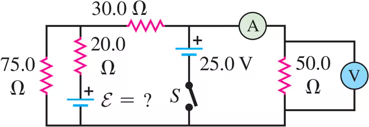
The 10.00 V battery in Fig. E26.28 is removed from the circuit and reinserted with the opposite polarity, so that its positive terminal is now next to point a. The rest of the circuit is as shown in the figure. Find the current in each branch.
1
views