Ch 32: AC Circuits
Knight Calc - Physics for Scientists and Engineers 5th Edition
Knight Calc5th EditionPhysics for Scientists and EngineersISBN: 9780137344796Not the one you use?Change textbook
Chapter 32, Problem 27b

A series RLC circuit has a 200 kHz resonance frequency. What is the resonance frequency if the capacitor value is doubled?

Verified step by step guidance
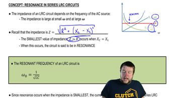
1
The resonance frequency of a series RLC circuit is given by the formula: f=12πLC, where f is the resonance frequency, L is the inductance, and C is the capacitance.
When the capacitor value is doubled, the new capacitance becomes C'=2C.
Substitute the new capacitance into the resonance frequency formula: f'=12πLC'.
Simplify the expression for the new resonance frequency: f'=12πL(2C). This simplifies further to f'=f√2, where f is the original resonance frequency.
Finally, use the given original resonance frequency of 200 kHz to express the new resonance frequency as f'=200√2 kHz. This is the new resonance frequency after doubling the capacitance.

Verified video answer for a similar problem:

This video solution was recommended by our tutors as helpful for the problem above.
Was this helpful?

Key Concepts

Here are the essential concepts you must grasp in order to answer the question correctly.

Resonance Frequency in RLC Circuits

The resonance frequency of a series RLC circuit is the frequency at which the inductive and capacitive reactances are equal in magnitude, resulting in maximum current flow. It is given by the formula f₀ = 1 / (2π√(LC)), where L is the inductance and C is the capacitance. At this frequency, the impedance of the circuit is minimized, and energy oscillates between the inductor and capacitor.
Recommended video:
Guided course
05:23
Resonance in Series LRC Circuits

Effect of Capacitance on Resonance Frequency

Doubling the capacitance in an RLC circuit affects the resonance frequency inversely. According to the resonance frequency formula, if the capacitance (C) is increased, the resonance frequency (f₀) decreases. This is because a larger capacitance allows more charge to be stored, which lowers the frequency at which the circuit resonates.
Recommended video:
Guided course
05:23
Resonance in Series LRC Circuits

Inductive and Capacitive Reactance

Inductive reactance (XL) and capacitive reactance (XC) are the opposition to current flow in inductors and capacitors, respectively. XL increases with frequency (XL = 2πfL), while XC decreases with frequency (XC = 1 / (2πfC)). At resonance, these two reactances are equal, leading to a condition where the total impedance is purely resistive, allowing for maximum current in the circuit.
Recommended video:
Guided course
08:02
Capacitors & Capacitance (Intro)