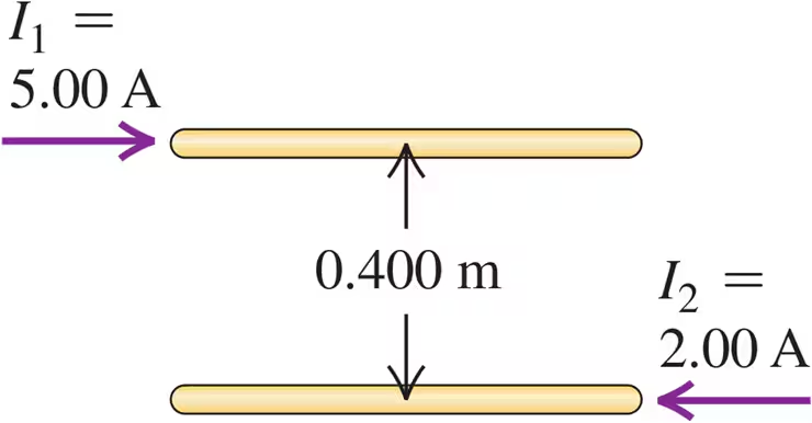
Four long, parallel power lines each carry 100 A currents. A cross-sectional diagram of these lines is a square, 20.0 cm on each side. For each of the three cases shown in Fig. E28.25, calculate the magnetic field at the center of the square.
Two long, parallel wires are separated by a distance of 0.400 m (Fig. E28.29). The currents I1 and I2 have the directions shown. Calculate the magnitude of the force exerted by each wire on a 1.20-m length of the other. Is the force attractive or repulsive?

Verified step by step guidance
Verified video answer for a similar problem:
Key Concepts
Magnetic Force Between Parallel Currents
Permeability of Free Space
Direction of Magnetic Forces
A closed curve encircles several conductors. The line integral around this curve is . If you were to integrate around the curve in the opposite direction, what would be the value of the line integral? Explain.
A solid conductor with radius a is supported by insulating disks on the axis of a conducting tube with inner radius b and outer radius c (Fig. E28.43). The central conductor and tube carry equal currents I in opposite directions. The currents are distributed uniformly over the cross sections of each conductor. Derive an expression for the magnitude of the magnetic field at points outside the tube (r > c).
Currents in dc transmission lines can be 100 A or higher. Some people are concerned that the electromagnetic fields from such lines near their homes could pose health dangers. For a line that has current 150 A and a height of 8.0 m above the ground, what magnetic field does the line produce at ground level? Express your answer in teslas and as a percentage of the earth's magnetic field, which is 0.50 G. Is this value cause for worry?
Two long, parallel wires are separated by a distance of 0.400 m (Fig. E28.29). The currents I1 and I2 have the directions shown. Each current is doubled, so that I1 becomes 10.0 A and I2 becomes 4.00 A. Now what is the magnitude of the force that each wire exerts on a 1.20 m length of the other?
