Textbook Question
FIGURE EX32.24 shows voltage and current graphs for an inductor. What is the value of the inductance L?
1
views

 Verified step by step guidance
 09:57
09:57 05:23
05:23 07:14
07:14FIGURE EX32.24 shows voltage and current graphs for an inductor. What is the value of the inductance L?
The peak current through an inductor is 10 mA. What is the peak current if the emf peak voltage is doubled (at the original frequency)?
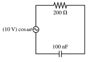
A high-pass RC filter is connected to an AC source with a peak voltage of 10.0 V. The peak capacitor voltage is 6.0 V. What is the peak resistor voltage?
A low-pass filter consists of a 100 μF capacitor in series with a 159 Ω resistor. The circuit is driven by an AC source with a peak voltage of 5.00 V. What is the crossover frequency fc?
What are VR and VC if the emf frequency in FIGURE EX32.19 is 2.5 kHz?
FIGURE EX32.24 shows voltage and current graphs for an inductor. What is the emf frequency f?