Ch. 30 - Inductance, Electromagnetic Oscillations, and AC Circuits
Giancoli Douglas - Physics for Scientists and Engineers 5th edition
Giancoli Douglas5th editionPhysics for Scientists and EngineersISBN: 9780137488179Not the one you use?Change textbook
Chapter 29, Problem 60

The frequency of the ac voltage source (peak voltage Vo) in an LRC circuit is tuned to the circuit’s resonant frequency f₀ = 1 / (2π√LC). (a) Show that the peak voltage across the capacitor is Vco = VoTo/ (2πτ), where To ( =1/fo) is the period of the resonant frequency and τ = RC is the time constant for charging the capacitor C through a resistor R. (b) Define β = To/ (2πτ) so that Vco = βVo. Then β is the “amplification” of the source voltage across the capacitor. If a particular LRC circuit contains a 2.0-nF capacitor and has a resonant frequency of 5.0 kHz, what value of R will yield β = 125?

Verified step by step guidance
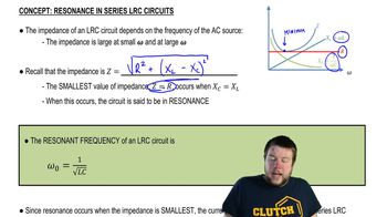
1
Step 1: Start with the given resonant frequency formula for the LRC circuit: f₀ = 1 / (2π√LC). The period of the resonant frequency is To = 1 / f₀. Substitute f₀ into To to express it in terms of L and C: To = 2π√LC.
Step 2: The time constant for charging the capacitor is defined as τ = RC. The voltage across the capacitor at resonance can be derived using the relationship between the source voltage and the capacitor's charging behavior. At resonance, the peak voltage across the capacitor is Vco = VoTo / (2πτ). Substitute τ = RC and To = 2π√LC into this equation to verify the given expression for Vco.
Step 3: Define the amplification factor β as β = To / (2πτ). Using the expressions for To and τ, substitute To = 2π√LC and τ = RC into β to express it in terms of L, C, and R. This gives β = √(L / C) / R.
Step 4: For part (b), substitute the given values into the expression for β. The capacitor value is C = 2.0 nF = 2.0 × 10⁻⁹ F, and the resonant frequency is f₀ = 5.0 kHz = 5.0 × 10³ Hz. Use f₀ = 1 / (2π√LC) to solve for L. Then, use β = √(L / C) / R and the given β = 125 to solve for the resistance R.
Step 5: Rearrange the equation β = √(L / C) / R to solve for R: R = √(L / C) / β. Substitute the calculated value of L, the given value of C, and β = 125 into this equation to find the required resistance R. Ensure all units are consistent during substitution.

Verified video answer for a similar problem:

This video solution was recommended by our tutors as helpful for the problem above.
Video duration:
8m
Was this helpful?

Key Concepts

Here are the essential concepts you must grasp in order to answer the question correctly.

Resonant Frequency

The resonant frequency (f₀) of an LRC circuit is the frequency at which the circuit naturally oscillates due to the inductance (L) and capacitance (C). It is given by the formula f₀ = 1 / (2π√LC), where L is the inductance in henries and C is the capacitance in farads. At this frequency, the impedance of the circuit is minimized, allowing maximum current to flow, which is crucial for understanding how voltage is distributed across circuit components.
Recommended video:
Guided course
05:23
Resonance in Series LRC Circuits

Time Constant (τ)

The time constant (τ) in an RC circuit is defined as τ = RC, where R is the resistance in ohms and C is the capacitance in farads. It represents the time it takes for the voltage across the capacitor to charge to approximately 63.2% of its maximum value when a voltage is applied. This concept is essential for analyzing how quickly the capacitor responds to changes in voltage, particularly during charging and discharging cycles.
Recommended video:
Guided course
08:59
Phase Constant of a Wave Function

Voltage Amplification (β)

Voltage amplification (β) in the context of an LRC circuit is defined as the ratio of the peak voltage across the capacitor (Vco) to the peak voltage of the source (Vo). It is expressed as β = To / (2π τ), where To is the period of the resonant frequency. This concept indicates how much the voltage across the capacitor is increased compared to the source voltage, which is critical for understanding the behavior of the circuit at resonance and its efficiency in energy storage.
Recommended video:
Guided course
07:14
RMS Current and Voltage
Related Practice