Ch. 30 - Inductance, Electromagnetic Oscillations, and AC Circuits
Giancoli Douglas - Physics for Scientists and Engineers 5th edition
Giancoli Douglas5th editionPhysics for Scientists and EngineersISBN: 9780137488179Not the one you use?Change textbook
Chapter 29, Problem 43

A 10.0-k Ω resistor is in series with a 34.0-mH inductor and an ac source. Calculate the impedance of the circuit if the source frequency is (a) 55.0 Hz; (b) 55.0 kHz.

Verified step by step guidance
1
Determine the formula for the impedance of an R-L series circuit. The total impedance \( Z \) is given by \( Z = \sqrt{R^2 + (X_L)^2} \), where \( R \) is the resistance and \( X_L \) is the inductive reactance.
Calculate the inductive reactance \( X_L \) using the formula \( X_L = 2 \pi f L \), where \( f \) is the frequency of the source and \( L \) is the inductance of the inductor. Perform this calculation for both \( f = 55.0 \ \text{Hz} \) and \( f = 55.0 \ \text{kHz} \).
Substitute the given values for \( R = 10.0 \ \text{k}\Omega = 10,000 \ \Omega \), \( L = 34.0 \ \text{mH} = 0.034 \ \text{H} \), and the calculated \( X_L \) for each frequency into the impedance formula \( Z = \sqrt{R^2 + (X_L)^2} \).
For part (a), use the calculated \( X_L \) at \( f = 55.0 \ \text{Hz} \) to find the impedance \( Z \).
For part (b), use the calculated \( X_L \) at \( f = 55.0 \ \text{kHz} \) to find the impedance \( Z \).

Verified video answer for a similar problem:

This video solution was recommended by our tutors as helpful for the problem above.
Video duration:
5m
Was this helpful?

Key Concepts

Here are the essential concepts you must grasp in order to answer the question correctly.

Impedance in AC Circuits

Impedance (Z) is the total opposition that a circuit offers to the flow of alternating current (AC) and is a combination of resistance (R) and reactance (X). It is expressed as Z = √(R² + X²), where R is the resistance and X is the reactance due to inductors or capacitors. Understanding impedance is crucial for analyzing AC circuits, as it affects the current and voltage relationship.
Recommended video:
Guided course
08:40
Impedance in AC Circuits

Inductive Reactance

Inductive reactance (X_L) is the opposition to the change in current flow through an inductor in an AC circuit, calculated using the formula X_L = 2πfL, where f is the frequency and L is the inductance. This concept is essential for determining how inductors behave at different frequencies, impacting the overall impedance of the circuit.
Recommended video:
Guided course
12:59
Mutual Induction

Series Circuit Behavior

In a series circuit, components are connected end-to-end, and the same current flows through each component. The total impedance is the sum of the individual resistances and reactances. This behavior is important for calculating the overall impedance in circuits with resistors and inductors, as it influences the voltage drop across each component and the total current in the circuit.
Recommended video:
Guided course
05:55
LRC Circuits in Series
Related Practice
Textbook Question

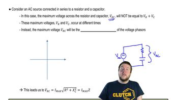
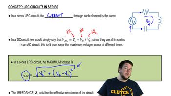
An ac voltage source is connected in series with a 2.0-μF capacitor and a 750-Ω resistor. Using a digital ac voltmeter, the voltage source is measured to be 4.0 V rms, and the voltages across the resistor and across the capacitor are found to be 3.0 V rms and 2.7 V rms, respectively. Determine the frequency of the ac voltage source. Why is the voltage measured across the voltage source not equal to the sum of the voltages measured across the resistor and across the capacitor?

2
views
Textbook Question

(II) A 25-mH coil whose resistance is 0.80 Ω is connected to a capacitor C and a 420-Hz source voltage. If the current and voltage are to be in phase, what value must C have?

2
views
Textbook Question

(II) Suppose that the U-shaped conductor and connecting rod in Fig. 29–12a are oriented vertically (but still in contact) so that the rod is falling due to the gravitational force. Find the terminal speed of the rod if it has mass m = 3.6 grams, length 𝓁 = 18 cm, and resistance R = 0.0013 Ω. It is falling in a uniform horizontal field B = 0.080 T. Neglect the resistance of the U-shaped conductor, and friction.

Textbook Question

A 1.50-k Ω resistor in series with a 370-mH inductor is driven by an ac power supply. At what frequency is the impedance double that of the impedance at 60.0 Hz?

Textbook Question

An average power output of 150 W is sent into a 4-Ω loudspeaker (see Fig. 25–14). What are the rms voltage and the rms current fed to the speaker at 1.0 W when the volume is turned down?

1
views
Textbook Question

(II) A capacitor is placed in parallel with some device, B, as in Fig. 30–18b, to filter out stray high-frequency signals, but to allow ordinary 60.0-Hz ac to pass through with little loss. Suppose that circuit B in Fig. 30–18b is a resistance R = 530 Ω connected to ground, and that C = 0.35 μF. Calculate the ratio of the capacitor’s current amplitude to the incoming current’s amplitude if the incoming current has a frequency of (a) 60.0 Hz; (b) 60.0 kHz.