Textbook Question
Suppose in Fig. 24–27 that C₁ = C₃ = 8.0μF, C₂ = C₄ = 16μF, and Q₃ = 21μC. Determine the voltage Vba across the combination.
1
views

 Verified step by step guidance
 08:02
08:02 08:53
08:53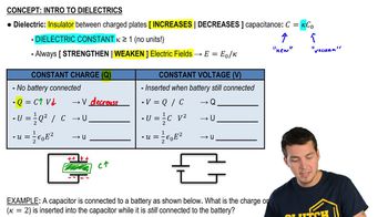 06:25
06:25Suppose in Fig. 24–27 that C₁ = C₃ = 8.0μF, C₂ = C₄ = 16μF, and Q₃ = 21μC. Determine the voltage Vba across the combination.
(II) A 7.7-μF capacitor is charged by a 185-V battery (Fig. 24–21a) and then is disconnected from the battery. When this capacitor (C₁) is then connected (Fig. 24–21b) to a second (initially uncharged) capacitor, C₂, the final voltage on each capacitor is 15 V. What is the value of C₂? [Hint: Charge is conserved.]
Small distances can be measured using a capacitor whose plate separation 𝓍 is variable. Consider an air-filled parallel-plate capacitor with fixed plate area A = 25 mm² separated by a variable distance 𝓍. Assume this capacitor is attached to a capacitance-measuring instrument which can measure capacitance C in the range 1.0 pF to 1000.0 pF with an accuracy of ∆C = 0.1 pF. Define ∆𝓍 to be the accuracy (magnitude) to which 𝓍 can be determined, and determine a formula for ∆𝓍.
In an electrostatic air cleaner (“precipitator”), the strong nonuniform electric field in the central region of a cylindrical capacitor (with outer and inner cylindrical radii Rₐ and R₆ ) is used to create ionized air molecules for use in charging dust and soot particles (Fig. 24–22). Under standard atmospheric conditions, if air is subjected to an electric field magnitude that exceeds its dielectric strength Eₛ ≈ 3.0 x 10⁶ N/C, air molecules will dissociate into positively charged ions and free electrons. In a precipitator, the region within which air is ionized (the corona discharge region) occupies a cylindrical volume of radius R that is typically five times that of the inner cylinder. Assume a particular precipitator is constructed with R₆ = 0.10 mm and Rₐ = 10.0 cm. In order to create a corona discharge region with radius R = 5.0 R₆, what potential difference V should be applied between the precipitator’s inner and outer conducting cylinders? [Besides dissociating air, the charged inner cylinder repels the resulting positive ions from the corona discharge region, where they are put to use in charging dust particles, which are then “collected” on the negatively charged outer cylinder.]