Ch. 28 - Sources of Magnetic Field
Giancoli Douglas - Physics for Scientists and Engineers 5th edition
Giancoli Douglas5th editionPhysics for Scientists and EngineersISBN: 9780137488179Not the one you use?Change textbook
Chapter 27, Problem 43

(II) Consider a straight section of wire of length d, as in Fig. 28–51, which carries a current I. (a) Show that the magnetic field at a point P a distance 𝑅 from the wire along its perpendicular bisector is


B=μ0I2πRd(d2+4R2)12B = \(\frac{\mu_0 I}{2\pi R}\) \(\frac{d}{(d^2 + 4R^2)^{\frac{1}{2}\)}}


(b) Show that this is consistent with Example 28–10 for an infinite wire.

Verified step by step guidance
1
Step 1: Begin by understanding the problem. Part (a) asks us to derive the magnetic field at a point P a distance R from the wire along its perpendicular bisector. Part (b) asks us to verify that the result is consistent with the magnetic field of an infinite wire. We'll use the Biot-Savart law for part (a) and compare the result to the formula for an infinite wire in part (b).
Step 2: For part (a), apply the Biot-Savart law, which states that the magnetic field d𝐵 due to a small segment of current-carrying wire is given by: dB=μIdlsinθ4πr2. Here, μ₀ is the permeability of free space, I is the current, dl is the length element of the wire, θ is the angle between dl and the vector pointing to the observation point, and r is the distance from dl to the observation point.
Step 3: Consider the geometry of the problem. The wire is of finite length d, and the point P is located at a distance R from the wire along its perpendicular bisector. Symmetry simplifies the calculation: the contributions to the magnetic field from opposite sides of the wire will add up in the same direction. Use trigonometry to express sinθ and r in terms of R, d, and the position along the wire.
Step 4: Integrate the Biot-Savart law over the length of the wire from -d/2 to +d/2. The integral will involve terms like dd2+4R2, which arise from the geometry of the problem. After performing the integration, simplify the result to obtain the magnetic field at point P: B=μId2πRd2+4R2.
Step 5: For part (b), compare the derived formula to the magnetic field of an infinite wire, which is given by B=μI2πR. As the length d approaches infinity, the term dd2+4R2 simplifies to 1, and the derived formula reduces to the infinite wire formula, confirming consistency.

Verified video answer for a similar problem:

This video solution was recommended by our tutors as helpful for the problem above.
Video duration:
15m
Was this helpful?

Key Concepts

Here are the essential concepts you must grasp in order to answer the question correctly.

Magnetic Field Due to a Current-Carrying Wire

The magnetic field generated by a straight current-carrying wire can be calculated using Ampère's Law. The magnetic field (B) at a distance (R) from the wire is directly proportional to the current (I) flowing through the wire and inversely proportional to the distance from the wire. This relationship is crucial for understanding how the magnetic field behaves around conductors.
Recommended video:
Guided course
09:57
Magnetic Force on Current-Carrying Wire

Biot-Savart Law

The Biot-Savart Law provides a method to calculate the magnetic field produced at a point in space by a small segment of current-carrying wire. It states that the magnetic field (dB) at a point is proportional to the current (I), the length of the wire segment (dl), and the sine of the angle between the wire segment and the line connecting the segment to the point, divided by the square of the distance from the segment to the point.
Recommended video:
Guided course
04:53
Biot-Savart Law with Calculus

Limit of Finite Wire to Infinite Wire

When analyzing the magnetic field of a finite wire, it is important to understand how it approaches the behavior of an infinite wire as the length of the wire increases. The magnetic field of an infinite wire is uniform and can be derived from the finite wire's magnetic field by taking the limit as the length approaches infinity, simplifying calculations and providing a clearer understanding of magnetic field behavior in practical applications.
Recommended video:
Guided course
07:59
Magnetic Field due to Finite Wire
Related Practice
Textbook Question

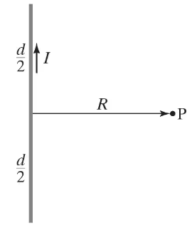
(III) Use the result of Problem 44 to find the magnetic field at point P in Fig. 28–53 due to the current in the square loop.


1
views
Textbook Question

(II) A circular conducting ring of radius 𝑅 is connected to two exterior straight wires at two ends of a diameter (Fig. 28–47). The current I splits into unequal portions as shown (unequal resistance) while passing through the ring. What is B\(\overrightarrow{B}\) at the center of the ring?


2
views
Textbook Question

Three long parallel wires are 3.5 cm from one another. (Looking along them, they are at three corners of an equilateral triangle.) The current in each wire is 9.50 A, but its direction in wire M is opposite to that in wires N and P (Fig. 28–57). Determine the magnetic force per unit length on each wire due to the other two.


1
views
Textbook Question

(III) A square loop of wire, of side d, carries a current I. (a) Determine the magnetic field B at points on a line (call it the 𝓍 axis) perpendicular to the plane of the square which passes through the center of the square (Fig. 28–56). Express B as a function of 𝓍, the distance from the center of the square. (b) For 𝓍 ≫ d, does the square appear to be a magnetic dipole? If so, what is its dipole moment?


1
views
Textbook Question

(II) A wire is formed into the shape of two half circles connected by equal-length straight sections as shown in Fig. 28–48. A current I flows in the circuit clockwise as shown. Determine (a) the magnitude and direction of the magnetic field at the center, C, and (b) the magnetic dipole moment of the circuit.

2
views
Textbook Question

(III) A coaxial cable consists of a solid inner conductor of radius R1, surrounded by a concentric cylindrical tube of inner radius R2 and outer radius R3 (Fig. 28–45). The conductors carry equal and opposite currents I₀ distributed uniformly across their cross sections. Determine the magnetic field at a distance R from the axis for: (a) R < R1; (b) R1 < R < R2; (c) R2 < R < R3; (d) R > R3. (e) Let I₀ = 1.50 A, R1 = 1.00 cm , R2 = 2.00 cm , and R3 = 2.50 cm Graph B from R = 0 to R = 3.00 cm.

1
views