Ch. 30 - Inductance, Electromagnetic Oscillations, and AC Circuits
Giancoli Douglas - Physics for Scientists and Engineers 5th edition
Giancoli Douglas5th editionPhysics for Scientists and EngineersISBN: 9780137488179Not the one you use?Change textbook
Chapter 29, Problem 99

To detect vehicles at traffic lights, wire loops with dimensions on the order of 2 m are often buried horizontally under roadways. Assume the self-inductance of such a coil is L = 5.0 mH and that it is part of an LRC circuit as shown in Fig. 30–40 with C = 0.10 μF and R = 38 Ω. The ac voltage has frequency f and rms voltage Vrms. (a) The frequency f is chosen to match the resonant frequency f₀ of the circuit. Find f₀ and determine what the rms voltage (VR)rms across the resistor will be when f = f₀. (b) Assume that f, C, and R never change, but that, when a car is located above the buried coil, the coil’s self-inductance decreases by 10% (due to induced eddy currents in the car’s metal parts). Determine by what factor the voltage (VR)rms decreases in the presence of a car in comparison to no car above the loop and thus how it detects the presence of a car. (c) Describe how the eddy currents induced in the car reduce L. [Hint: Recall Eq. 30–4, the definition of inductance.]

Verified step by step guidance
1
Step 1: To find the resonant frequency f₀, use the formula for the resonant frequency of an LRC circuit: f₀ = 1 / (2π√(LC)). Substitute the given values for L = 5.0 mH (5.0 × 10⁻³ H) and C = 0.10 μF (0.10 × 10⁻⁶ F) into the formula.
Step 2: At resonance, the impedance of the circuit is purely resistive, meaning the voltage across the resistor (VR)rms is equal to the total rms voltage (V)rms supplied to the circuit. Use Ohm's law and the resonance condition to determine (VR)rms.
Step 3: When a car is above the coil, the self-inductance L decreases by 10%. Calculate the new inductance L' as L' = 0.9 × L. Then, recalculate the resonant frequency f₀' using the formula f₀' = 1 / (2π√(L'C)).
Step 4: The voltage across the resistor (VR)rms decreases when the circuit is no longer at resonance due to the change in inductance. Use the formula for the voltage across the resistor in an LRC circuit, considering the new frequency and impedance, to determine the factor by which (VR)rms decreases.
Step 5: Eddy currents induced in the car reduce L because they create opposing magnetic fields that counteract the original magnetic field in the coil. This phenomenon is explained by Lenz's law, which states that the induced currents oppose the change in magnetic flux, effectively reducing the coil's inductance.

Key Concepts

Here are the essential concepts you must grasp in order to answer the question correctly.

Resonant Frequency

The resonant frequency (f₀) of an LRC circuit is the frequency at which the inductive reactance (XL) equals the capacitive reactance (XC). This condition allows the circuit to oscillate with maximum amplitude, leading to a significant increase in the voltage across the resistor (VR). The formula for resonant frequency is f₀ = 1 / (2π√(LC)), where L is the inductance and C is the capacitance.
Recommended video:
Guided course
05:23
Resonance in Series LRC Circuits

Inductance and Eddy Currents

Inductance (L) is a property of a coil that quantifies its ability to store energy in a magnetic field when an electric current flows through it. When a conductive object, like a car, is placed near the coil, it induces eddy currents in the car's metal parts. These currents create their own magnetic field, which opposes the original magnetic field of the coil, effectively reducing the coil's inductance by about 10% in this scenario.
Recommended video:
Guided course
12:59
Mutual Induction

Voltage Across the Resistor

In an LRC circuit, the voltage across the resistor (VR) is influenced by the circuit's impedance, which changes with frequency. At resonance, the impedance is minimized, leading to maximum current and thus maximum voltage across the resistor. When the inductance decreases due to the presence of a car, the impedance increases, resulting in a decrease in VR, which can be measured to detect the car's presence.
Recommended video:
Guided course
07:14
RMS Current and Voltage
Related Practice
Textbook Question

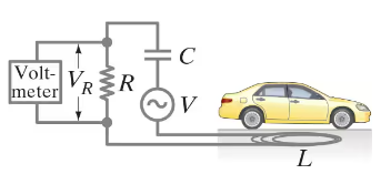
In a plasma globe, a hollow glass sphere is filled with low-pressure gas and a small spherical metal electrode is located at its center. Assume an ac voltage source of peak voltage Vo and frequency f is applied between the metal sphere and the ground, and that a person is touching the outer surface of the globe with a fingertip, whose approximate area is 1.0 cm². The equivalent circuit for this situation is shown in Fig. 30–36, where RG and RP are the resistances of the gas and the person, respectively, and C is the capacitance formed by the gas, glass, and finger. (a) Determine C assuming it is a parallel-plate capacitor. The conductive gas and the person’s fingertip form the opposing plates of area A = 1.0 cm². The plates are separated by glass (dielectric constant K = 5.0) of thickness d = 2.0 mm. (b) In a typical plasma globe, f = 12 kHz. Determine the reactance XC of C at this frequency in MΩ. (c) The voltage may be Vo = 2500 V. With this high voltage, the dielectric strength of the gas is exceeded and the gas becomes ionized. In this “plasma” state, the gas emits light (“sparks”) and is highly conductive so that RG << XC. Assuming also that RP << XC, estimate the peak current that flows in the given circuit. Is this level of current dangerous? (d) If the plasma globe operated at f = 1.0 MHz, estimate the peak current that would flow in the given circuit. Is this level of current dangerous?


<IMAGE>

2
views
Textbook Question

The RC circuit shown in Fig. 30–39 is a low-pass filter because it passes low-frequency ac signals with less attenuation than high-frequency ac signals. (a) Show that the voltage gain is A=Vout/Vin=1/(4π2f2R2C2+1)12A = V_{\(\text{out}\)}/V_{\(\text{in}\)} = 1/(4\(\pi\)^2 f^2 R^2 C^2 + 1)^{\(\frac{1}{2}\)} (b) Discuss the behavior of the gain A for f → 0 and f → ∞.

1
views
Textbook Question

For the circuit shown in Fig. 30–35, show that if the condition R₁ R₂ = L/C is satisfied then the potential difference between points a and b is zero for all frequencies.

2
views