Ch. 28 - Sources of Magnetic Field
Giancoli Douglas - Physics for Scientists and Engineers 5th edition
Giancoli Douglas5th editionPhysics for Scientists and EngineersISBN: 9780137488179Not the one you use?Change textbook
Chapter 27, Problem 45

(III) Use the result of Problem 44 to find the magnetic field at point P in Fig. 28–53 due to the current in the square loop.


Verified step by step guidance
1
Step 1: Recall the result of Problem 44, which provides the formula for the magnetic field at a point due to a current-carrying wire segment. The formula for the magnetic field at a point due to a straight wire segment is derived using the Biot-Savart law.
Step 2: Analyze the geometry of the square loop in Fig. 28–53. The loop consists of four straight wire segments, and the magnetic field at point P is the vector sum of the contributions from each segment. Identify the distances and angles relevant to each segment.
Step 3: Apply the Biot-Savart law to calculate the magnetic field contribution from each segment. The Biot-Savart law is given by: B=μ0I4πr²dlsin(θ), where μ₀ is the permeability of free space, I is the current, r is the distance from the wire to the point, dl is the length element of the wire, and θ is the angle between dl and the vector pointing to the point.
Step 4: For each segment of the square loop, calculate the magnetic field contribution at point P. Consider symmetry and direction of the current to simplify the calculations. Note that some components may cancel out due to symmetry.
Step 5: Sum the contributions from all four segments to find the total magnetic field at point P. Ensure that the vector directions are properly accounted for in the summation.

Verified video answer for a similar problem:

This video solution was recommended by our tutors as helpful for the problem above.
Video duration:
10m
Was this helpful?

Key Concepts

Here are the essential concepts you must grasp in order to answer the question correctly.

Magnetic Field

The magnetic field is a vector field that describes the magnetic influence on moving electric charges, electric currents, and magnetic materials. It is represented by the symbol B and is measured in teslas (T). The direction of the magnetic field is defined as the direction a north pole would move, and its strength varies with distance from the source of the magnetic field.
Recommended video:
Guided course
05:30
Magnetic Fields and Magnetic Dipoles

Biot-Savart Law

The Biot-Savart Law provides a mathematical description of the magnetic field generated by a steady electric current. It states that the magnetic field dB at a point in space is directly proportional to the current I and the length element dl of the wire, and inversely proportional to the square of the distance r from the wire to the point. This law is essential for calculating the magnetic field due to complex current configurations.
Recommended video:
Guided course
04:53
Biot-Savart Law with Calculus

Superposition Principle

The superposition principle in electromagnetism states that the total magnetic field created by multiple sources is the vector sum of the individual fields produced by each source. This principle allows for the analysis of complex systems by breaking them down into simpler components, making it easier to calculate the resultant magnetic field at a given point due to various current-carrying conductors.
Recommended video:
Guided course
03:32
Superposition of Sinusoidal Wave Functions
Related Practice
Textbook Question

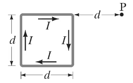
(II) A circular conducting ring of radius 𝑅 is connected to two exterior straight wires at two ends of a diameter (Fig. 28–47). The current I splits into unequal portions as shown (unequal resistance) while passing through the ring. What is B\(\overrightarrow{B}\) at the center of the ring?


2
views
Textbook Question

In Fig. 28–57 the top wire is 1.00-mm-diameter copper wire and is suspended in air due to the two magnetic forces from the bottom two wires. The current is 35.0 A in each of the two bottom wires. Calculate the required current in the suspended wire (M).

1
views
Textbook Question

Three long parallel wires are 3.5 cm from one another. (Looking along them, they are at three corners of an equilateral triangle.) The current in each wire is 9.50 A, but its direction in wire M is opposite to that in wires N and P (Fig. 28–57). Determine the magnetic force per unit length on each wire due to the other two.


1
views
Textbook Question

(III) A square loop of wire, of side d, carries a current I. (a) Determine the magnetic field B at points on a line (call it the 𝓍 axis) perpendicular to the plane of the square which passes through the center of the square (Fig. 28–56). Express B as a function of 𝓍, the distance from the center of the square. (b) For 𝓍 ≫ d, does the square appear to be a magnetic dipole? If so, what is its dipole moment?


1
views
Textbook Question

(II) Consider a straight section of wire of length d, as in Fig. 28–51, which carries a current I. (a) Show that the magnetic field at a point P a distance 𝑅 from the wire along its perpendicular bisector is


B=μ0I2πRd(d2+4R2)12B = \(\frac{\mu_0 I}{2\pi R}\) \(\frac{d}{(d^2 + 4R^2)^{\frac{1}{2}\)}}


(b) Show that this is consistent with Example 28–10 for an infinite wire.

1
views
Textbook Question

(II) A wire is formed into the shape of two half circles connected by equal-length straight sections as shown in Fig. 28–48. A current I flows in the circuit clockwise as shown. Determine (a) the magnitude and direction of the magnetic field at the center, C, and (b) the magnetic dipole moment of the circuit.

2
views